Laser Cutting Aluminum: Make Everything Perfect

Laser Cutting Aluminum: Make Everything Perfect

Every manufacturing method has its unique mechanism, application and final product. Aluminum cutting is an extraordinary process, known for its versatility, precision and suitability for complex designed aluminum components. Let’s delve into the aluminum laser cutting process, its practical applications and the factors that affect this process.

What is the laser cutting?

Laser Cutting of Fibre Metal Aluminium Laser cutting is a manufacturing process that uses laser beams to cut various materials, including plastics, metals and composite materials. The process involves using a laser cutting machine to generate a highly focused and intense laser beam with high thermal energy, which melts, evaporates or burns the material being cut by the laser. Laser cutting of aluminium is as common as other manufacturing processes such as CNC machining. It effectively handles the design of complex aluminium parts without compromising on accuracy and precision.

What are the advantages of laser cutting aluminum?

This is a cost-effective process with many advantages and disadvantages. The advantages of this process are as follows:

Flexibility in the thickness of aluminum parts

Laser cutting of aluminum is compatible with alloys of different thicknesses without losing consistency and accuracy. However, this depends on the type of laser you are using (discussed below). For example, the 6000W CO2 laser cutting machine can cut 16mm thick aluminum plate, while the 4500W laser cutting machine can effectively cut 12mm thick aluminum plate. The flexibility of the process allows laser cutting of aluminum components for a variety of industrial and domestic applications.

Repeatability and efficiency

The laser cutting process is precise, consistent and precise because it is controlled by a computer. As a result, industries that produce in large quantities, especially those that use multiple aluminum components, can integrate it into their manufacturing operations to optimize production times and increase productivity.

Excellent thermal conductivity

Aluminum has good heat dissipation properties, which can be a problem when laser cutting. Faster cooling due to heat dissipation can make it difficult for cutting materials to reach higher temperatures. One solution is to obtain high-speed laser cutters with high pulse frequencies that can melt the surface before dissipating heat.

Aluminum laser cutting preparation

The laser cutting process for aluminum is unique and requires a perfect understanding of the process to operate successfully. For a successful laser cutting procedure, there are three main steps:

Material selection and preparation
Proper material selection and preparation are critical to the success of the operation. Therefore, choose the aluminum alloy that is suitable for the process, and consider the thickness, surface condition and composition of the part. For example, the Aluminum 5000 series contains magnesium, which reduces the reflective properties of the material and reduces the laser power of cutting aluminum parts, making it suitable for any laser cutting machine.
After selecting the right material, it is prepared by cleaning to ensure the best absorption of the laser beam and avoid inconsistencies and splatters when cutting. Cleaning is the removal of dirt, grease, oil and other contaminants that affect the cutting process.

Determine the best laser cutting parameters
The use of optimal laser cutting parameters in aluminum cutting helps to improve accuracy and process efficiency. The parameters to be considered for aluminum laser cutting include laser power, lens focal length, cutting speed and beam diameter.
The setting of good cutting parameters depends on the aluminum alloy and thickness, cutting speed, while balancing factors such as cutting speed, edge mass and heat affected zone. After the determination, the aluminum foil can be fixed and positioned.
Aluminum parts must be stable, flat and safe, which can be achieved through equipment such as fixtures and flanges. The choice of fixture depends on the size, shape and other dimensional parameters of the aluminum sheet. Proper fastening ensures that sudden movement or vibration of aluminum components will not lead to inaccuracies. In addition, it ensures that the machine follows the pre-programmed part of the cad file, thus ensuring accuracy.


Laser cutting technology of aluminum

Aluminum laser cutting can use different types of lasers, the most common choices are CO2 lasers, fiber lasers, and YAG lasers. Each type of laser has unique characteristics and is able to cut aluminum parts made of different alloys.

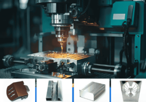
Application of aluminum laser cutting parts

High precision laser cutting machine, high precision laser cutting machine, laser cutting aluminum applications are diverse, including:

Automobile industry
The automotive industry uses laser-cut aluminum components to manufacture parts for body panels, engines, chassis and other components, thanks to lightweight materials, resulting in improved energy efficiency, process precision and complex design and precise shape of the brackets.

Aerospace industry
The aerospace industry uses aluminum components because of their light weight and high strength. Suitable for the manufacture of aircraft structures, interior panels, fuel systems, landing gear, engine components and other aerospace components. The industry also uses the laser cutting process because of its precision, due to the strict tolerances required by the industry.

Electronic and electrical industry
Aluminum laser cutting parts are suitable for the manufacture of electronic components such as electronic housings, radiators, PCB components (printed circuit boards). The industry relies more on the heat dissipation of materials and extremely high process accuracy, allowing them to achieve tight tolerances.

Industrial machinery
Laser cutting aluminum is suitable for manufacturing industrial machinery parts such as frames, structural parts, brackets, gears, etc. The high precision and durability of these components contribute to the overall performance and reliability of industrial machinery.

Click on the email consultation below to start your exclusive aluminum laser cutting service now!

Let's Start A New Project Today

Latest Blog Posts

Check out the latest industry trends and take inspiration from our updated blogs, giving you a fresh insight to help boost your business.

CNC Machining of Aluminum: Properties and Applications by TOP Prototype

CNC Machining of Aluminum: Properties and Applications by TOP Prototype Aluminum, with its unique combination of physical and mechanical properties, …

Tapped Holes vs Threaded Holes – Differences and Comparison

Tapped Holes vs Threaded Holes – Differences and Comparison In mechanical manufacturing, assembly, and precision engineering, internal threaded holes serve as the “connective tissue” of components, enabling secure fastening, precise positioning, and stable load transmission. Tapped holes and threaded holes, two widely applied types of internal threaded structures, are often conflated due to their overlapping functional goals. Yet their divergence in processing principles, structural integrity, and practical performance is substantial—differences that directly affect product reliability, production costs, and service life. This article systematically distinguishes the two, enriches the discussion with industrial practices and material science facts, simplifies complex terminology, and reconstructs the logical framework to clarify their characteristics, advantages, and application boundaries for engineering practitioners. 1. Definitions and Core Structural Traits 1.1 Tapped Holes: Direct Thread Formation in Base Material A tapped hole is an internal threaded hole formed by the tapping process, where a specialized cutting tool (tap) cuts or forms threads on the inner wall of a pre-drilled pilot hole. Unlike indirect threading methods, tapped holes integrate threads directly into the workpiece’s base material—no auxiliary inserts or reinforcements are involved. Taps operate on a subtractive principle: they remove excess material from the pilot hole’s inner surface to form standardized thread profiles, such as metric (M series), unified coarse (UNC), or unified fine (UNF) threads, with precision grades ranging from 2B (general purpose) to 3B (high precision) for imperial threads. This integration with the base material means tapped holes’ performance is inherently tied to the workpiece’s material properties. For instance, in medium-carbon steel (e.g., 45# steel) or 6061 aluminum alloy—materials with moderate ductility and strength—tapped holes deliver reliable thread retention. They are widely adopted in scenarios where the workpiece itself can bear fastening loads, avoiding the need for additional components. 1.2 Threaded Holes: A Broad Category with Indirect Threading Dominance The term “threaded hole” is a generic concept encompassing all holes with internal threads, including tapped holes. In industrial practice, however, it primarily refers to holes where threads are formed indirectly—most commonly via threaded inserts. These inserts, made of high-strength materials like 304 stainless steel or titanium alloy, are installed into pre-drilled holes to provide the internal thread interface, decoupling thread performance from the workpiece’s base material. Beyond insert-based threading, threaded holes also include structures formed by thread rolling, casting, or injection molding. Thread rolling, for example, is used for high-volume production of ductile materials like copper or low-carbon steel, forming threads through plastic deformation rather than cutting. Cast or molded threaded holes are integral to composite parts (e.g., glass-fiber reinforced plastic) or plastic components, where threads are pre-designed in the mold to eliminate post-processing. 2. Core Differences in Processing Principles and Operations The fundamental gap between tapped holes and threaded holes lies in their thread formation mechanisms—each dictating processing efficiency, precision limits, and material applicability. Simplifying these mechanisms reveals why each is preferred in specific scenarios. 2.1 Tapped Holes: Two-Step Subtractive Processing Tapping follows a rigid two-step workflow: first, drilling a pilot hole with a diameter strictly matched to the target thread (e.g., a 6.8mm pilot hole for an M8×1.25 tap); second, cutting threads using a hand tap (for small batches or manual operations) or machine tap (for automated production on CNC lathes, milling machines, or dedicated tapping centers). Critical process parameters directly impact thread quality: tap speed (typically 10-30 m/min for steel, 20-50 m/min for aluminum), feed rate (matched to thread pitch to avoid thread distortion), and lubrication (cutting oil for ferrous metals, cutting fluid for non-ferrous metals to reduce friction and prevent burring). Brittle materials like gray cast iron (HT200) or zirconia ceramic require specialized spiral-flute taps to evacuate chips and avoid cracking, while ductile materials like copper demand straight-flute taps for smooth chip removal. 2.2 Threaded Holes: Indirect Formation with Diversified Methods Insert-based threaded holes, the most common type, follow a three-step process: drilling a hole matching the insert’s outer diameter (e.g., a 10.2mm hole for an M8 helical insert), installing the insert via pressing, self-tapping, or adhesive bonding, and verifying thread accuracy. Helical wire inserts (HeliCoils), for example, are coiled stainless steel wires with a diamond cross-section—when installed, they expand to lock into the pre-drilled hole, distributing fastening loads over a larger surface area to prevent thread stripping. Other threading methods for threaded holes have clear niche applications: thread rolling achieves higher thread strength (up to 30% higher than cut threads due to work hardening) and is used for high-volume parts like automotive bolts; casting/molding eliminates post-processing but is limited to parts with simple thread geometries, as complex threads may cause mold release issues. 3. Performance Comparison and Practical Application Scenarios Evaluating strength, precision, cost, and maintainability reveals the practical trade-offs between tapped holes and threaded holes. Grounded in industrial data and real-world cases, this comparison helps engineers make evidence-based selections. …

Analysis of Causes and Solutions of Surface Roughness Issues in CNC Machining

Analysis of Causes and Solutions of Surface Roughness Issues in CNC Machining In CNC machining, surface roughness is critical—it directly …

Scroll to Top

Contact Us

Upload Your Files to Get Instant Quote and DFM Feedback
(Please attach 2D CAD drawings and 3D CAD models in any format including STEP,STP, IGES, DWG, PDF, STL, PDF, JPG , ZIP, RAR, etc